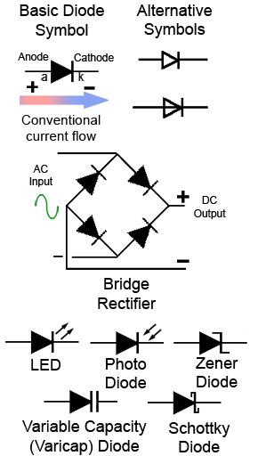
Verwunderlich Led Schematic Symbol Polarity Ebenbild. You may also place a k for cathode adjacent to the cathode. If you use surface mount diodes or leds, you probably understand the challenges involved in correctly and consistently indicating diode polarity. There are a handful of identifiers for sometimes it's easiest to just use a multimeter to test for polarity.

Some publications use the old resistor symbol
Schematic symbols have been standardized by two different guidelines: But you don't need to memorize them all. The preferred method is to place the diode schematic symbol in the silk screen. Now, your circuit is complete, and we have duplicated the circuit that is shown in the starter kit schematics, but we need to change the software. There are a handful of identifiers for sometimes it's easiest to just use a multimeter to test for polarity. How to find polarity on an smd led chip. Fritzing may alow you to do that, it may have some. I'll show you in a minute why just part of. Circuit symbols are used in circuit diagrams showing how a circuit is connected together. I used a symbol of a diode in a box for the cells, which i assume is based off this model commonly used to and if i use the diode symbol, how is the polarity?