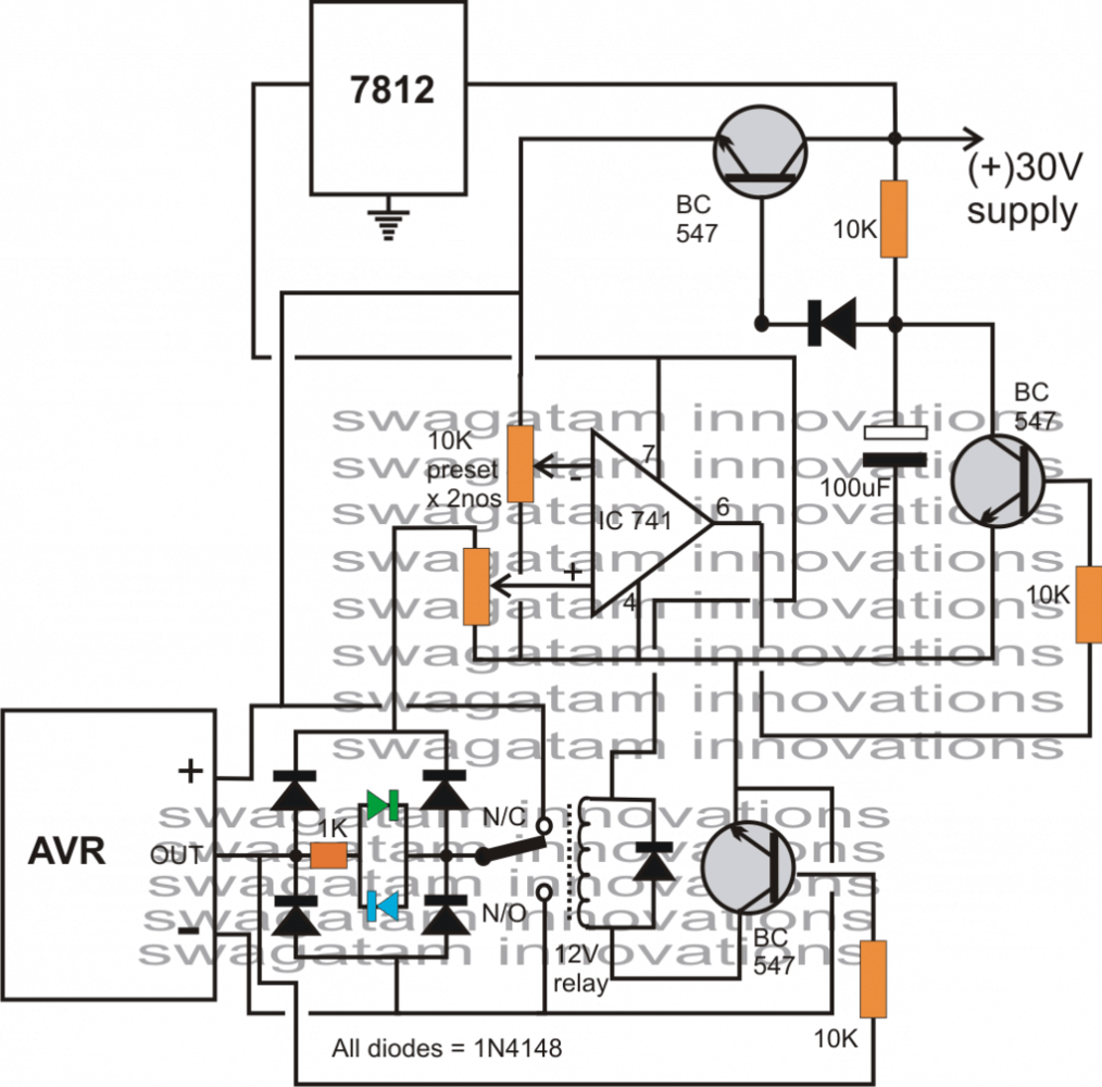
Wunderbar Schematic Diagram Automatic Voltage Regulator Ebenbild. The diagram below shows a generic avr implementation. Automatic voltage regulator (avr) maintains the generator terminal voltage at a given valve automatically by changing the excitation hence automatic voltage regulators are employed to maintain terminal voltage constant always. The voltage to be regulated is derived from the line ur and vr of the a.c.

Circuit, construction within automatic voltage regulator schematic diagram, image size 878 x 788 px, and to view image details please click the image.
It may possibly work for different gens. Generator automatic voltage regulator datasheets context search. It basically consists of a main exciter which excites the alternator field to control the output voltage. For this matter an appropriate voltage regulator circuit is designed which can operate up to capacity. A voltage regulator is a system designed to automatically maintain a constant voltage level. It works on the principle of detection of errors. An automatic voltage regulator circuit is quite well used where voltage supply is only 120vac. It may possibly work for different gens. And own full set of equipment and technology for mass production including parts like hardware, circuit board, coil by. Full wave regulator schematic, motorcycle regulator, hid charging, regulator diagram, hid conversion, 5 wire regulator, rr schematic, lowbatt a full wave regulator is a type of regulator mostly found on small motorcycle that can enhance the charging system of motorcycle battery.