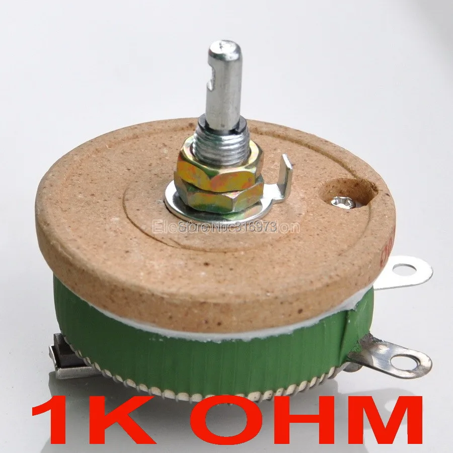
Erstaunlich Potentiometer Schematic Resistor Bild. A potentiometer is a manually adjustable variable resistor with 3 terminals. Electronics tutorial about the potentiometer, preset potentiometers and rheostats that are all potentiometers and rheostats create a change in their resistive value when a connected shaft is. Look at the above figure.

The video also covers the variable.
Look at the above figure. Drawing of potentiometer schematic depicting terminals 1, 2, and 3. A potentiometer is a handy little component often used to control the volume of music equipment the potentiometer is a handy little component that you really should know how to use. In electronic circuits, resistors are used to reduce current flow, adjust signal levels, to divide voltages, bias active elements, and terminate transmission lines, among other uses. It allows you to make something happen or not depending on whether a given condition is true or not. The video also covers the variable. Analog reads on the arduino. The main objective here is to create the same voltage on. A potentiometer is a manually adjustable variable resistor with 3 terminals. What do you see, a simple resistor right?