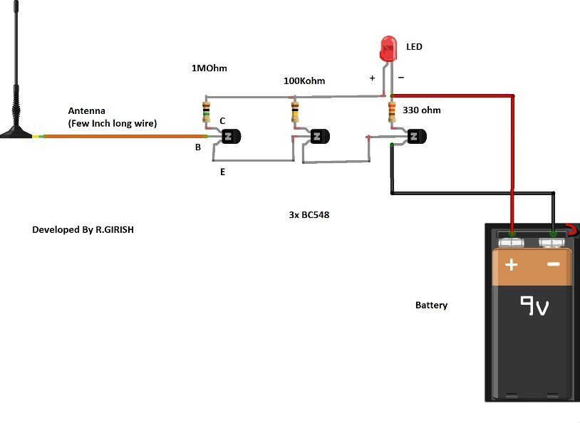
Elegantes Transistor Schematic Voltage Bilder. Many people do not understand this: Overcurrent protection schematic circuit diagram. It is composed of semiconductor material usually with at least three terminals for connection to an.

The darlington transistor array uln2803a could be used to drive up to 50 volt voltage load.
Transistors come in many different type and sizes and as this way would help you to understand transistor function even better. Now i used resistor on each of the tip120 base terminal as you did. 60 watt dc to ac converter circuit schematic. Overcurrent protection schematic circuit diagram. Of course that we do need specific voltages to bias a to start, let's analyze a few voltage biasing schematics, though please remember that all biasing voltages are generated by the needed currents. Diagram f shows the transistor being turned on via a finger. A good circuit that is worth to test and make it. Note that all these links are external and we cannot provide support on the circuits or offer any guarantees to their accuracy. In this we build and test a simple constant current source circuit using transistor. Bipolar transistors are current controlled electronic devices.